More on Transformers
Transformers, like many other devices suffers from energy loss through heat. Heat loss from various sources include heating effect of the current in the coil. Power loss (I * I * R) through heat generated by current through the copper wires can be reduced by using thicker wires of low resistance. This is more important particularly for the coil carrying the high current at low voltage. The cost of copper wire and the size and weight of the transformer limit the gauge of wire that can be used.
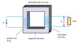
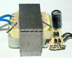
Another major loss of the transformer is the heat effect of Eddy currents. Eddy or Foucault currents are induced within a solid conducting (normally iron) core when varying filed passes through this core. The currents induced within the core are similar to that by which current are induced in straight wires and coils. These currents, know as eddy or Foucault currents, circulate in closed loops within the conducting iron core and cause heat to be generated in the core. To minimise eddy currents, the solid conducting core is usually replaced by laminated pieces of the same material (iron for this case). Each layer of the material is insulated from the next by a thin coating of enamel so that a very high resistance is offered to currents that may be produced within the block of material as a whole. In this way, the circulation of eddy currents is restricted, and the loss of energy minimised. Hence it is to reduce eddy currents that a bundle of insulated soft-iron wires is used in the induction coil and a laminated iron core for the transformer.
Another major loss of the transformer is the heat effect of Eddy currents. Eddy or Foucault currents are induced within a solid conducting (normally iron) core when varying filed passes through this core. The currents induced within the core are similar to that by which current are induced in straight wires and coils. These currents, know as eddy or Foucault currents, circulate in closed loops within the conducting iron core and cause heat to be generated in the core. To minimise eddy currents, the solid conducting core is usually replaced by laminated pieces of the same material (iron for this case). Each layer of the material is insulated from the next by a thin coating of enamel so that a very high resistance is offered to currents that may be produced within the block of material as a whole. In this way, the circulation of eddy currents is restricted, and the loss of energy minimised. Hence it is to reduce eddy currents that a bundle of insulated soft-iron wires is used in the induction coil and a laminated iron core for the transformer.
Energy is used in the process of magnetising the iron core and reversing this magnetism every time the current reverses, also heats the iron core. This loss is sometimes know as hysteresis loss. It can be reduced by using very soft iron (as a core) that can be easily magnetised and demagnetised by the primary coil.
Finally, some of the magnetic field lines produced by the primary coil do not link with the secondary coil, reducing the e.m.f. induced in the secondary coil. The core of the transformer is designed for maximum linkage between the primary and secondary coils; common method is to wind the secondary coil on top of the primary coil, the iron core must always form a closed loop of iron.
Finally, some of the magnetic field lines produced by the primary coil do not link with the secondary coil, reducing the e.m.f. induced in the secondary coil. The core of the transformer is designed for maximum linkage between the primary and secondary coils; common method is to wind the secondary coil on top of the primary coil, the iron core must always form a closed loop of iron.
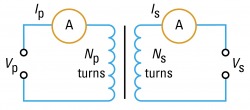
Diagram representation of a transformer:
The figure below shows how a transformer is represented in circuit designs. Some designs go further by differentiating between step-up and step-down transformers by displaying the different number turns in the primary and secondary coils. E.g. for a step-up transformer, the secondary coil would drawn with more turns than the primary coil.
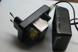
Hand Phone Charger
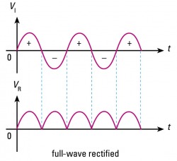
A typical mobile phone charger would contain a transformer, a full-wave rectifier and a filter normally consist of a capacitor and other component. The full-wave rectifier consists of 2 pairs of diode connected in a particular order so that at any half cycle of an AC source, only 2 diodes would be in forward bias.
Title.
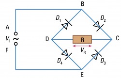
Full-wave rectifier